Selecting an injection mold is a major investment, and the design affects part quality, production speed, and maintenance costs. For buyers, mold design for injection molding is not just a technical drawing. It is a set of decisions that shapes how reliably a part can be made. A thin rib, sharp corner, or misplaced gate may look minor on screen. In production, each can contribute to warping, visible marks, or difficult ejection.
A useful review starts with the part itself. Check wall thickness, draft angles, ribs, undercuts, and the proposed parting line. Ask where the gate will sit and how the cooling channels will reach thick sections. These details influence cycle time and appearance. They also affect how easily technicians can clean and service the tool. Requesting a mold-flow analysis can help reveal filling or cooling concerns before steel is cut, though simulation results still depend on accurate inputs.
Material matters, too. A resin’s shrinkage, flow behavior, and temperature requirements can change the mold layout. Buyers should share the expected resin, annual volume, tolerances, and cosmetic requirements with the mold maker. Ask how the design supports inspection and future repairs, not only the first sample run. A clear design review can prevent expensive revisions, but no checklist catches everything. That uncertainty is real. Experienced suppliers can explain their assumptions and show relevant tooling examples; buyers should still question details that seem vague.
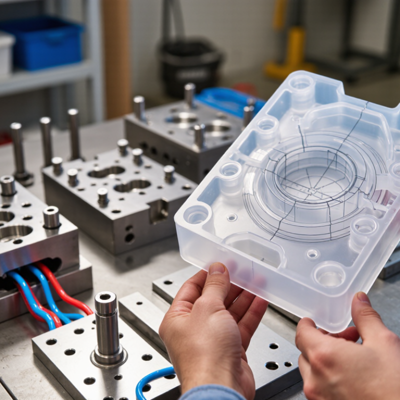
Before discussing mold geometry, define what the part must do. Record its key dimensions, mating surfaces, expected loads, operating temperature, and visible-face requirements. A drawing alone may not show how the part will be assembled or handled. Include the resin family, color, surface texture, and acceptable variation where known. These details influence wall thickness, draft, gate location, and shrinkage allowances. Small details matter. If requirements are still uncertain, flag them rather than treating estimates as fixed specifications.
Tips: Share a marked-up part drawing, expected annual volume, and critical-to-fit dimensions. Note where weld lines, gate marks, or parting lines would be unacceptable. A simple photo of the assembly can clarify how the part is used.
Set production objectives alongside part requirements. State the target quantity, expected tool life, delivery timing, and whether production may grow. These goals affect cavity count, tooling complexity, automation, and inspection planning. Ask the molder which assumptions drive the estimate, and request a review of risky features before finalizing the design. Early estimates are provisional; that is not a flaw, but a reason to test assumptions. A trial run may reveal that a tolerance is unnecessarily tight, or that a cosmetic surface needs a different gate strategy. Be ready to revise.
Resin selection should begin with the part’s job, not just its purchase price. A flexible cover, a hot-water fitting, and a clear window need different properties. Check operating temperature, chemical exposure, impact needs, and appearance requirements against the resin data sheet. Treat its shrinkage values as estimates. Actual results also depend on flow length, mold temperature, and processing conditions. Test it early.
Part geometry can make a suitable resin difficult to mold. Keep wall thickness as even as practical; abrupt changes may cause sink marks or uneven cooling. Use generous internal radii where sharp corners would restrict flow or concentrate stress. Ribs can add stiffness, but overly thick ribs may leave visible sinks on the opposite surface. Their proportions should be reviewed with the chosen material and tooling plan.
Draft angles, gate location, and flow direction deserve attention before the mold is cut. A deep textured wall may need more draft than a smooth one. Gate placement can affect weld-line position, surface appearance, and fiber orientation in reinforced resins. In a design review, a clean CAD model can still hide a stubborn filling problem. Mold-flow analysis can flag risks, though it cannot replace trial molding. We sometimes focus too much on nominal dimensions; real parts also shift with cooling and process variation.
Choosing a mold type starts with production risk. A prototype or bridge mold can test fit and resin behavior before committing to hardened steel. A production mold costs more upfront but suits repeated, high-volume runs. Family molds can form several part designs together, yet uneven part sizes may complicate filling and cooling. Test the layout before approving the tool.
Cavity count affects output, but more cavities also demand tighter process control. A single-cavity mold is easier to tune when dimensions are critical or demand is uncertain. Multi-cavity tools can reduce unit cost when demand is stable and every cavity fills consistently. Grand View Research estimated the global injection molding market at USD 284.4 billion in 2023, in its 2024 market analysis. That scale makes tooling decisions consequential, but the estimate does not predict an individual buyer’s savings.
Tool material changes cooling, wear, and maintenance needs. MatWeb material data list thermal conductivity near 167 W/m·K for 6061-T6 aluminum; typical P20 mold steel is around 29 W/m·K. Exact values vary by grade and condition. Aluminum can move heat quickly, but it may wear sooner under abrasive resins or long runs. Steel often offers greater durability. Ask the moldmaker to specify the steel grade, hardness, expected shot life, and cooling layout. A higher cavity count looks efficient on paper. It can disappoint when cavity balance is poor.
Top Mold Design Tips for Injection Molding Buyers
Cooling, venting, and ejection choices affect cycle time, part quality, and tool maintenance. Ask how the proposed cooling layout follows the part’s thick and thin sections. Water channels placed far from a thick boss may leave that area hot after the rest has cooled. Uneven cooling can cause sink marks or warping. It is worth reviewing a channel diagram, not just accepting a claim of “balanced cooling.” Temperature readings during a trial can reveal more than a tidy drawing.
Small details matter. Check that cooling circuits are accessible for cleaning and that their flow can be checked separately. A complex layout is not automatically better. Sometimes a simpler circuit is easier to maintain, though it may leave local hot spots that require testing.
Venting deserves equal attention. Trapped air near the end of fill can burn the plastic or leave short shots. Ask where vents sit, how they will be cleaned, and whether their depth suits the resin and part geometry. Ejection should also be reviewed against visible surfaces and delicate features. Pins can leave marks or distort a warm part; sleeves or a stripper plate may suit some shapes better. There is no universal answer. Request a trial plan that records fill behavior, part release, and any sticking or deformation. Even then, the first test may not settle every question. That is useful evidence, not a failure.
| Design Area | What to Assess | Practical Starting Point | Questions for the Mold Maker | Potential Warning Sign |
|---|---|---|---|---|
| Cooling layout | Channel coverage near thick sections, ribs, bosses, and other heat-retaining areas. | Use a balanced cooling layout. As an initial rule of thumb, channel spacing is often around 2–3 times the channel diameter; confirm placement against the part geometry and cooling analysis. | Are the cooling circuits shown on the mold layout, and can each circuit be tested independently for flow and leakage? | Long, unevenly cooled sections or critical areas with no clear cooling path. |
| Cooling performance | Expected temperature uniformity, flow distribution, and access for cleaning or maintenance. | Ask for circuit flow and pressure-drop checks. Keep circuits practical to balance and service; avoid relying on a single long circuit to cool widely separated areas. | What cooling assumptions are used for the cycle-time estimate, and how will water flow be verified during mold trials? | A cycle-time promise without documented cooling assumptions or a circuit plan. |
| Conformal or specialty cooling | Whether standard drilled channels can adequately reach complex or deep features. | Consider baffles, bubblers, or conformal channels where geometry limits conventional cooling. Check manufacturability, pressure drop, cleaning access, and cost before selecting them. | What measurable cycle-time or part-quality benefit is expected compared with conventional cooling? | Specialty cooling is proposed without a clear performance rationale or maintenance plan. |
| Parting-line vents | Vent locations near the last areas to fill and around features where air may become trapped. | Provide vents that let displaced air escape while limiting plastic flash. Vent depth is resin- and process-dependent, so confirm it with material guidance and molding trials rather than using one depth for every resin. | Where are the predicted air traps, and how will vent dimensions be validated for the specified resin? | No venting plan for end-of-fill areas, or a fixed vent depth applied to all materials. |
| Venting details | Vents in ribs, deep pockets, blind features, and around inserts or slides. | Use appropriate venting paths, such as vented inserts or ejector-pin vents, where parting-line vents cannot reach trapped air. Ensure vents can be inspected and cleaned. | How will the design reduce burn marks, short shots, and trapped-gas damage during production? | Burn marks or incomplete filling are expected to be corrected only by increasing injection pressure. |
| Ejection layout | Whether ejectors support the part evenly, especially beneath broad, flexible, or deep-draw areas. | Place ejectors on structurally suitable surfaces and distribute them to reduce local stress and distortion. Confirm that pin marks are acceptable on the finished part. | Are ejector positions included in the mold drawing, and have they been reviewed against cosmetic and functional surfaces? | Too few ejectors, concentrated loading, or pin marks on critical appearance surfaces. |
| Draft and release | Draft on walls, ribs, and textured surfaces, plus potential sticking caused by shrinkage or surface finish. | Provide draft on mold-release surfaces. The required angle depends on material, texture, wall depth, and geometry; textured surfaces generally need more draft than smooth surfaces. | Have draft angles been checked for the specified surface texture and material shrinkage? | Near-zero draft on deep or textured walls without a release-risk assessment. |
| Ejection stroke and timing | Available stroke, part clearance, and coordination between ejectors, slides, and other moving components. | Verify that the part can clear the core without interference and that the ejection sequence is compatible with the machine and mold design. | What is the required ejection stroke, and how will the mold prevent ejection before slides or other mechanisms are clear? | Insufficient clearance, possible mechanism collision, or no defined ejection sequence. |
| Trial validation | Evidence that cooling, venting, and ejection work together under the intended material and process conditions. | Review trial parts for warpage, sink, burn marks, short shots, flash, drag marks, and ejector deformation. Record process settings and cooling-flow checks. | Which acceptance criteria will be used, and will trial results include dimensional and visual checks? | Approval based only on cycle time or a small sample without documented quality criteria. |
Before choosing an injection mold, ask for test records from a production-like trial. Review the resin, cycle time, cavity balance, and part measurements. Request samples from multiple shots, not just one attractive part. Check for flash around the parting line, sink marks near thick sections, and uneven ejection. A polished report is useful, but it may miss problems that appear after longer runs.
Maintenance planning and supplier support matter after the first shipment. The U.S. Department of Energy’s Operations & Maintenance Best Practices guide reports typical predictive-maintenance savings of 8–12% over preventive maintenance. That figure covers general industrial equipment, not injection molds specifically, but it shows why condition checks deserve attention. Ask who tracks wear on vents, slides, and ejector pins, and how quickly replacement parts can be supplied. Get response times in writing. A checklist can still miss a developing issue; review it against actual downtime and repair records.
Tip: Agree on a mold-maintenance schedule, trial acceptance criteria, and escalation contact before production. Keep dated photos of wear points. They make supplier discussions more precise.
Verify mold testing, maintenance planning, and supplier support before approving a production mold.
How to use this chart: It counts the buyer verification items listed for each area; it is a checklist, not an industry benchmark.
During trials, review dimensional results, process-window evidence, fill balance, part quality, and approved samples. Confirm maintenance tasks and intervals with the mold supplier, based on the mold design and actual production conditions. Agree on technical contacts, escalation steps, and repair or spare-part support before production.