
Why Are Worm Gears Used?

Worm Gears are used when a design needs substantial speed reduction in a compact space. A worm, shaped like a screw, drives a toothed wheel, often turning an output shaft at a right angle. This arrangement can fit neatly inside machinery where a larger gear train would be awkward. It also allows a small input gear to produce slower, higher-torque output. That matters.

You may find worm gear drives in conveyors, lifting equipment, packaging machines, and adjustable worktables. Their smooth, steady motion can reduce operating noise, especially when the unit is properly aligned and lubricated. In some designs, friction helps resist reverse motion when the input stops. But self-locking is not guaranteed; it depends on factors such as lead angle, materials, lubrication, and load. Engineers should verify it rather than assume it.

There is a trade-off. The teeth slide against each other, creating friction and heat. Under demanding conditions, this can mean lower efficiency and more attention to lubricant choice, temperature, and maintenance. A worm drive may be a poor fit when continuous high-speed operation or minimal energy loss is essential. I have seen compactness treated as the whole answer; it is not. Load, duty cycle, mounting space, noise limits, and access for servicing all deserve a place in the decision. Understanding these strengths and limits explains why worm gears remain useful, and why selecting one should begin with the actual operating conditions.
Why Are Worm Gears Used?

What a Worm Gear Is and How Its Components Fit Together

Why Are Worm Gears Used?
What a Worm Gear Is and How Its Components Fit Together

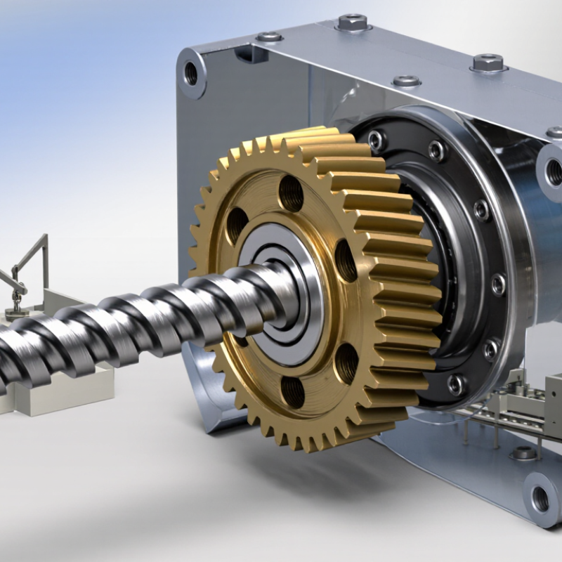
A worm gear set pairs a threaded shaft, called the worm, with a toothed wheel. The shafts usually meet at a right angle, making the assembly useful where space is limited. As the worm turns, its threads push the wheel’s teeth forward. The wheel’s tooth count and the worm’s number of starts determine the reduction ratio. A single-start worm can turn a many-toothed wheel slowly, producing high output torque.

The set also depends on its housing, bearings, and lubricant. The housing holds the shafts in alignment; bearings support rotation and help control movement. Lubricant forms a film between sliding tooth surfaces, where friction can generate heat. The International Energy Agency’s 2011 report, Energy-Efficiency Policy Opportunities for Electric Motor-Driven Systems, estimates that motor-driven systems use about 45% of global electricity. That wider energy context makes losses worth checking, even in a small reducer. Worm drives can be compact, but their efficiency varies with geometry, speed, load, and lubrication. Self-locking is not guaranteed; it depends on design and operating conditions.

Tips: Check the gear ratio, rated load, and lubrication guidance before installation. After a short run, feel for unusual heat and listen for rough noise. Small details matter. Alignment may look acceptable by eye, yet a slight offset can wear the teeth unevenly.

Why Are Worm Gears Used?

Worm gear reduction ratio with a 60-tooth wheel

A worm gear pairs a screw-like worm with a toothed wheel. The reduction ratio equals the wheel’s tooth count divided by the number of starts on the worm. With a 60-tooth wheel, a single-start worm gives a 60:1 ratio, while a four-start worm gives a 15:1 ratio. This arrangement can provide substantial speed reduction in a compact layout.

How Motion and Torque Pass Through a Worm Gear Set

Why Are Worm Gears Used?

A worm gear set transfers motion through a screw-shaped worm meshing with a toothed wheel. The worm’s rotation pushes the wheel tooth by tooth, changing the direction of motion, often by 90 degrees.

A single stage can provide substantial speed reduction in a compact space. Industrial selection tables commonly list ratios from about 5:1 to 100:1, though the usable range depends on geometry and load.

Torque rises as speed falls, but not without losses. Friction at the sliding tooth contact creates heat, so lubrication, alignment, and duty cycle matter.

Machinery’s Handbook describes worm-gear efficiency as strongly dependent on lead angle and friction; engineering references commonly place practical efficiencies around 50–90 percent. That spread is wide. A low-lead design may resist back-driving, while a higher-lead design can transmit power more efficiently.

For example, a motor turning a small worm can drive a slow conveyor roller, but sustained heavy loading may overheat the reducer. Check temperature and lubricant condition under real operating conditions; paper calculations can miss messy details.

Key Advantages of Worm Gears in Mechanical Systems

Worm gears are chosen when a design needs a large speed reduction in a small space. A single stage can commonly provide ratios from about 5:1 to 100:1, according to AGMA’s Design Manual for Cylindrical Wormgearing (AGMA 6022-C93). The worm shaft and wheel also turn through a right angle, which can simplify layouts in hoists, conveyors, and compact positioning equipment. Less packaging bulk can mean easier installation beside a frame or beneath a work surface.

There is a trade-off. Sliding contact between the worm and wheel creates friction, so efficiency depends on factors such as lead angle, lubrication, and operating load. AGMA’s design guidance treats these factors as essential to rating a worm set; a high reduction ratio alone does not predict performance. That detail is easy to overlook. In a real assembly, a hot gearbox or unsuitable lubricant may undermine the expected benefits. Worm drives can resist back-driving in some configurations, but this should be verified for the specific design, not assumed as a safety feature. For engineers, the practical advantage is concentrated reduction and a flexible shaft arrangement, balanced against heat, lubrication needs, and efficiency.

Why Are Worm Gears Used? — Key Advantages of Worm Gears in Mechanical Systems
Advantage or characteristic How it works Where it is useful Design consideration
High reduction in one stage A worm with a small number of starts can drive a worm wheel with many teeth, producing a substantial speed reduction in a single gear stage. Compact drives that need low output speed and increased output torque, such as lifts, conveyors, and positioning equipment. The resulting output torque is also affected by input power, gear geometry, lubrication, and efficiency.
Right-angle shaft arrangement Worm gears commonly transmit motion between shafts arranged at right angles, allowing the drive layout to turn through 90 degrees. Machinery where the motor and driven shaft need to be positioned perpendicular to each other. Check shaft alignment, mounting space, and the required direction of rotation when selecting the arrangement.
Compact drive packaging A large speed reduction can often be achieved without several successive gear stages, which can simplify the overall drive package. Enclosed gearboxes and installations with limited space for a multi-stage transmission. Compactness depends on the required ratio, torque rating, thermal limits, and gearbox design.
Smooth, quiet operation The worm’s thread engages progressively with the wheel teeth, generally producing smooth motion and low noise when the gears are properly designed and lubricated. Equipment where operating noise and vibration are important considerations. Noise and vibration also depend on manufacturing accuracy, mounting stiffness, wear, and operating conditions.
Potential resistance to back-driving Friction and a low lead angle can make some worm gear sets difficult to drive from the wheel side. Applications that benefit from reduced tendency for a load to move the drive backward when power is removed. Self-locking is not guaranteed. It depends on the gear geometry, friction, lubrication, wear, and load; use a suitable brake when load holding is safety-critical.
Useful for controlled motion The reduction ratio lowers output speed and can provide fine movement when the input is driven in a controlled manner. Adjustment mechanisms, indexing equipment, and other low-speed positioning tasks. Backlash, torsional compliance, and load variation should be considered where precise positioning is required.
Trade-off: efficiency and heat Sliding contact between the worm and wheel creates friction. Worm gear efficiency varies with design and operating conditions and may be lower than that of comparable spur or helical gear drives. Suitable when compact reduction, shaft layout, or resistance to back-driving matters more than maximum efficiency. Account for lubrication, heat dissipation, duty cycle, and the manufacturer’s rated operating limits.

Common Applications Across Industry and Everyday Equipment

Why Are Worm Gears Used?

Common Applications Across Industry and Everyday Equipment

Worm gear drives pair a screw-like worm with a toothed wheel. They can deliver substantial speed reduction in a compact, right-angle arrangement. That layout suits equipment where space is limited and controlled movement matters. Less speed, more torque.

Factory and Industrial Uses

On factory floors, worm gearboxes often drive conveyors, packaging equipment, and rotary tables. A conveyor may need to move heavy products slowly without taking up much room. Rotary tables use the gearing to position parts in measured steps. Valve actuators also use worm drives to turn valves gradually. Some designs resist back-driving, but this depends on the gear geometry, load, and lubrication. Never treat that feature as a safety brake.

Everyday Equipment and Trade-Offs

Worm gears also appear in hand winches, adjustable seating, window blinds, and some workshop machinery. A person turning a crank can raise or reposition a load with controlled effort. The trade-off is friction: sliding contact can create heat and reduce efficiency compared with some other gear types. Correct lubricant and regular checks matter. In practice, a worn or poorly lubricated drive may become noisy before it fails, though that warning is easy to miss.

Design Factors That Determine When a Worm Gear Is Suitable

Why Are Worm Gears Used?

Design Factors That Determine When a Worm Gear Is Suitable

A worm gear can provide a large speed reduction in a compact space. Its screw-like worm meshes with a toothed wheel, often turning a fast motor output into slower, higher-torque motion. This arrangement suits equipment with limited room, such as compact lifts, positioning tables, and conveyor drives. But the ratio alone does not determine whether it is a good choice. Check the required output speed, torque, duty cycle, and available mounting space together.

Sliding contact between the worm and wheel creates friction. That can mean lower efficiency and more heat than some other gear arrangements, especially during continuous operation. Lubrication, materials, alignment, and operating temperature all affect service life. A worm drive may resist back-driving, but this is not guaranteed under every load or condition. Do not rely on it as the sole means of holding a load. That detail is easy to overlook. And costly.

Tips: Compare efficiency and heat at the actual operating speed, not just at startup. Confirm lubrication needs and expected duty cycle. If the load must stay put when power is off, assess a suitable brake or other holding method separately. A small test under realistic conditions can reveal problems that calculations miss.