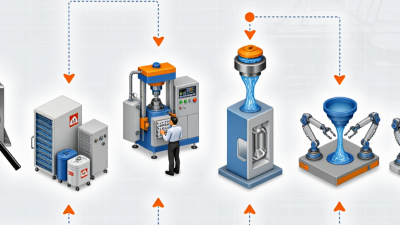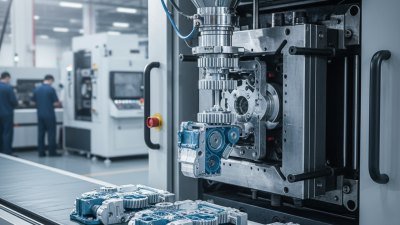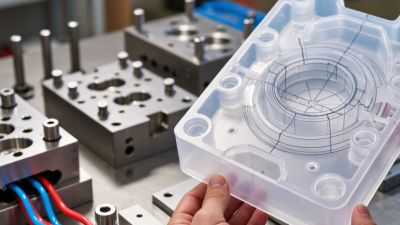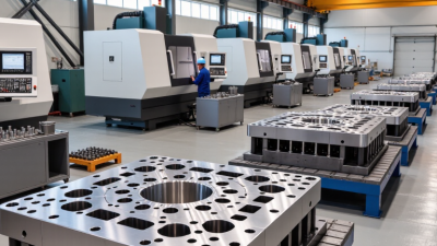
Injection tooling shapes the quality, cost, and consistency of molded parts long before production begins. It includes the mold, cooling channels, gates, runners, and the systems used to eject finished components. Small design choices matter. A poorly placed gate can leave visible marks or create uneven filling. Inadequate cooling may lengthen cycle times and cause warping. These issues can turn a promising part into a costly production problem.
Good injection tooling helps manufacturers produce repeatable parts at scale. It can reduce scrap, stabilize dimensions, and support reliable output across many cycles. Tool design also affects material flow, maintenance needs, and the time required to change or repair a mold. The details are concrete: a technician checks venting, a process engineer studies pressure data, and a molded sample is measured against its drawing. No tool is perfect. Even a carefully designed mold may need adjustment after real material and machine conditions reveal what simulations missed. That is worth admitting.
For product teams, injection tooling is not merely a production expense. It is an early engineering decision with effects that can last throughout a product’s manufacturing life. The right approach depends on part geometry, material, expected volume, tolerances, and budget. A low-cost tool may suit a short run, while demanding production needs stronger construction and careful maintenance planning. Details matter. Understanding these trade-offs helps teams ask better questions, reduce avoidable surprises, and choose tooling that fits the part—not just the initial quote.
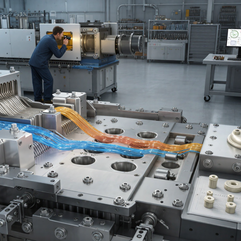
Injection tooling is the equipment that shapes molten plastic into repeatable parts. It includes more than a steel mold. A typical tool has a mold base, a cavity and core, alignment pins, cooling channels, and an ejector system. The cavity forms the part’s outside; the core creates its inner features. Small details matter. A misplaced vent can trap air, while a rough surface may leave visible marks.
During a molding cycle, the tool closes and the machine pushes heated resin through a nozzle, runner, and gate. The gate directs material into the cavity. Cooling channels carry water or another controlled coolant through the tool, drawing heat away until the part is firm enough to release. Then ejector pins or plates push it out. It sounds simple. In practice, fill speed, pressure, temperature, and cooling time interact, so a change in one setting can alter dimensions or surface finish.
Tooling design also considers parting lines, draft angles, shrinkage, and expected production volume. These choices affect cycle time, maintenance, and the risk of sticking or warping. For example, a deep, narrow rib may cool unevenly and resist ejection. Engineers often review simulations and trial shots, then adjust vents, gates, or cooling paths. Not every prediction holds. A real tool can reveal a flaw that drawings missed, which is why measured samples and documented changes matter.
Injection tooling is not just a cavity that shapes plastic. Its design affects dimensions, surface finish, and how consistently parts repeat from cycle to cycle. ISO 20457:2018, the standard for tolerances in plastic moulded parts, defines seven tolerance groups, TG1–TG7. The range matters: tighter requirements need closer control of steel, machining, and process conditions. A small mismatch at a shutoff can leave a visible flash line or force extra trimming.
Cooling layout, gate position, venting, and ejection all influence quality. Uneven cooling can pull a flat panel into a slight bow; a poorly placed gate can leave a weld line near a load-bearing feature. These effects often appear together, so changing one tool detail may shift another. Tooling teams should review part geometry, resin shrinkage data, and inspection requirements before cutting steel. Still, simulations are not guarantees. Real resin and machine behavior can expose assumptions that looked sound on screen.
Tips: Put critical dimensions on the drawing, not just “tight tolerance.” Check cooling balance and vent locations during the design review. Keep a few trial parts for dimensional comparison; one sample is rarely enough.
Injection tooling shapes both production speed and manufacturing cost. A well-designed mold fills evenly, cools predictably, and releases parts without excessive delays. Even a few seconds saved per cycle can add up across thousands of shots. Cooling channels matter: poor placement may leave thick areas warm, extending cycle time and increasing the risk of warping. Small details count.
Tooling choices also influence scrap, maintenance, and downtime. A durable mold may require more investment upfront, yet consistent dimensions can reduce rejected parts and costly adjustments. Thoughtful venting and gate placement help prevent defects and make production more stable. Still, a spreadsheet can make these trade-offs look cleaner than they are. Resin behavior, machine settings, and operator routines can change actual results. Trial runs and routine inspections provide useful evidence before production scales.
Tips: Review cycle time, scrap rate, and maintenance records together. Check for uneven cooling or wear around gates. Ask the molder to explain assumptions behind cost estimates; estimates can miss real shop-floor variation.
Why Is Injection Tooling Important?
Why Reliable Tooling Matters for High-Volume Production
High-volume production depends on tools that produce consistent parts, shift after shift. A mold must hold its dimensions under repeated heat, pressure, and clamping. Even a slight change in cooling can affect part size or surface finish. Small details matter. Reliable tooling helps reduce scrap, unplanned stops, and adjustments between runs.
Good tooling is designed for the material, part geometry, and expected production rate. Stable cooling channels help control cycle times and reduce uneven shrinkage. Vents, gates, and ejector pins need careful placement to prevent trapped air, visible marks, or damaged parts. When these features are poorly matched to the job, operators may spend time correcting problems the tool created. That is costly.
Tooling quality also depends on maintenance, not just initial design. Scheduled inspections can catch worn shutoffs, clogged vents, or loose components before defects spread across a full batch. Teams should track repairs and recurring process changes; those records can reveal a tool-related issue. Yet no tool stays perfect forever. A design may work well in testing but prove harder to clean or maintain on the production floor. That gap deserves honest review.
Why Is Injection Tooling Important?
Key Factors in Selecting and Maintaining Injection Tooling
Injection tooling controls part accuracy, surface finish, and cycle consistency. Selection should start with resin, annual volume, geometry, and required tolerances. A glass-filled resin can wear a cavity faster than an unfilled grade. Cooling layout matters too: uneven temperatures can leave sink marks or warp thin walls. Check steel hardness, vent locations, ejection access, and expected shot count before approving a design. Small details matter. A polished cavity alone cannot guarantee stable output.
Maintenance needs a schedule, not just a response to visible defects. Record cycles, resin changes, repairs, and dimensional checks. Clean vents and inspect parting lines before residue becomes flash or trapped gas. The Manufacturing Institute’s 2024 workforce study projected that U.S. manufacturing may need 3.8 million workers by 2033, with 1.9 million positions at risk of going unfilled. Clear tooling records help teams retain process knowledge when experienced technicians are scarce. Still, a checklist cannot replace judgment; unusual wear deserves investigation.
Tips: Keep a dated photo log of cavity wear. Track cycle counts, and inspect cooling channels during planned service. Compare first-off parts with approved measurements after every major repair.
| Factor | Why It Matters | Selection Considerations | Maintenance Practice | Useful Checks or Indicators |
|---|---|---|---|---|
| Part requirements and tolerances | The tool must produce parts that meet the drawing, fit, appearance, and functional requirements consistently. | Review critical dimensions, material shrinkage, wall thickness, draft, and cosmetic surfaces before finalizing the tool design. | Inspect samples and cavity surfaces after changes to the process or tool; document dimensional results over time. | First-article measurements, capability studies, flash, sink marks, warpage, and dimensional drift. |
| Tool material and expected production volume | Tool material influences wear resistance, repairability, lead time, and the tool’s suitability for the planned production demand. | Match tool steel or aluminum tooling to resin abrasiveness, production volume, part geometry, and required surface finish. | Check for corrosion, wear, cracked components, and damage around shutoffs and parting surfaces; follow appropriate cleaning and storage procedures. | Wear at gates and slides, cavity surface condition, corrosion spots, and the trend in reject or repair rates. |
| Cavity count and layout | Cavity count affects output per cycle, tool size, balancing, maintenance effort, and the cost of producing each part. | Choose a layout that suits demand and can fill consistently. Multi-cavity tools require attention to runner balance and cavity-to-cavity variation. | Track defects by cavity number and inspect gates, vents, and moving components across all cavities. | Cycle output, cavity-specific scrap, part-weight variation, and differences in fill or cooling. |
| Cooling system | Effective, uniform cooling helps control cycle time and reduces uneven shrinkage and warpage. | Consider channel placement, access for cleaning, water quality, and temperature uniformity near thick or critical areas. | Check flow and leaks; clean channels when deposits or restricted flow are detected, and maintain water treatment as required. | Inlet and outlet temperatures, flow rate, pressure drop, cooling time, and part warpage. |
| Venting and gas management | Vents allow displaced air and gases to escape as the cavity fills; inadequate venting can contribute to burns, short shots, or poor surface quality. | Locate vents near end-of-fill regions and other areas where air may become trapped. Vent dimensions must suit the resin and process. | Clean vents carefully and inspect them for blockage, wear, or damage without changing their dimensions unintentionally. | Burn marks, hesitation, incomplete fill, trapped-gas evidence, and recurring defects at the same locations. |
| Gates and runners | The feed system influences filling, weld-line position, pressure requirements, material waste, and part appearance. | Consider gate type and location, resin behavior, part geometry, gate vestige requirements, and whether a hot or cold runner is appropriate. | Inspect gates and runner components for wear, blockage, leakage, and damage during scheduled tool checks. | Fill consistency, gate blush, hesitation, vestige quality, runner waste, and signs of leakage. |
| Moving components and shutoffs | Slides, lifters, ejectors, and shutoffs enable complex geometry but add alignment, wear, and lubrication requirements. | Assess access for servicing, component strength, motion sequence, and the risk of parting-line flash or interference. | Clean and lubricate components according to the tool and lubricant specifications; inspect for binding, galling, and abnormal wear. | Unusual noise, slow or inconsistent movement, ejector marks, flash, and visible scoring. |
| Preventive maintenance and records | Planned care can identify wear before it causes unplanned downtime or a large batch of nonconforming parts. | Set inspection tasks and intervals according to tool design, resin, operating conditions, and production history. | Record cycles, repairs, cleaning, component replacements, and inspection findings; verify the tool after maintenance. | Maintenance history, cycle count, recurring faults, downtime, scrap rate, and post-maintenance sample approval. |
| Note: Inspection intervals and acceptance limits should be defined for the specific tool, resin, part requirements, and operating conditions. | ||||